
| Main Menu - click above |


One of the first electronic circuits I built (in the late sixties) was an "Electronic Candle." It was a simple circuit with a phototransistor mounted near to a small light bulb. If a lit match was brought up to the bulb, the phototransistor was illuminated and switched on a second transistor, arranged as a darlington pair. The bulb then lit up and it then illuminated the phototransistor. The bulb remained lit, after withdrawal of the match, because of optical feedback. By interrupting the light with the fingers, the bulb could be snuffed out.
Last week I received an Arduino. It's destined for a specific project and I nearly got badly sidetracked. Having uploaded "blink" to ensure the IDE and Arduino were ok, I had a quick look at the examples in the IDE. "AnalogInOutSerial" looked interesting, and the electronic candle circuit from nearly fifty years ago appeared in my mind... In a matter of minutes I could make the Arduino into a modern day electronic candle!
I thought it would be interesting to contrast the utter simplicity of the original - a precisely arranged assembly of arsenic doped germanium, indium, copper, lead-tin alloy and tungsten in argon - with the Arduino, and the mind-boggling internal complexity of the ATmega328 microcontroller.
More on the Arduino electronic candle later in this post. First, what I remember of the original -
PHOTOTRANSISTOR ELECTRONIC CANDLE
Hopefully this is correct, my memory from several decades.... what was I writing?

The OCP71 PNP phototransistor - a "modded" OC71, see below.
The ASY 26 can be any PNP transistor capable of taking the bulb current.
The bulb - mine was a tiny indicator filament lamp.
"MAKING" THE PHOTOTRANSISTOR
The OC71 was an early glass encapsulated transistor, introduced in 1954 . It consisted of a tiny slice from a crystal of germanium, grown from a melt with an extremely small addition of arsenic. This dopant resulted in the crystal being an n-type semiconductor. Pellets of indium metal were bonded onto each side of the slice using a precisely controlled oven (below indium's melting point, 157°C). This caused indium atoms to diffuse into the crystal lattice for a short distance, resulting in a shell of p-type semiconductor around the indium pellets. An alloy junction PNP transistor.


OCP71 photos by Andy Dingley
Collector View. Side View. Emitter View
Wires led from the crystal and pellets, and the assembly was encapsulated inside a 15mm long glass tube in silicone grease. The glass was painted black for the OC71, but some transistors were left naked. Tarted up with a sexy little blue plastic skirt, the OC71 then became the OCP71 PNP Phototransistor, which was sold for six times more than the bog standard OC71. See advert below.
Not surprisingly, many electronics enthusiasts converted early OC71s into the phototransistor variant simply by scraping the paint off. So many in fact, that the manufacturers (Mullard) began filling the bastards with completely opaque white grease, to stop this practice and to continue ripping off folk! I remember smashing the glass tubes and removing the offending grease with carbon tetrachloride.


Advert from Practical Electronics 1968 May

This from the Mullard Transistor Circuits book,
concerning the OCP71 and why the emitter side was the most sensitive -
This is an excellent reference book from 1960, full book here
PHOTORESISTOR ELECTRONIC CANDLE
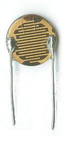
LDR07 CdS photoresistor
The cadmium sulphide is the dark material
The photoresistor is a light-dependent resistor (LDR). A semiconductor such as cadmium sulphide has a high resistance in darkness - a few megohms. When illuminated, its resistance dramatically falls to a couple of hundred ohms.
The discovery of photoresistance (or photoconductance), in 1873, by Willoughby Smith as announced in Nature -
From page 303, Nature, Volume 7, February 1873
Electronic Candle
from the April 1968 issue of
Practical Electronics magazine


ARDUINO ELECTRONIC CANDLE
(using a thermonuclear bomb to crack a walnut)
This is a very open ended set of observations, since I only spent an hour or so on it. The Arduino moved on to a more practical application. For those who are curious, it couldn't be simpler to reproduce and experiment with.
HARDWARE


SOFTWARE
The Arduino IDE has the program "AnalogInOutSerial" in its examples folder.
// These constants won't change. They're used to give names
// to the pins used:
const int analogInPin = A0; // Analog input pin that the photoresistor is attached to
const int analogOutPin = 9; // Analog output pin that the LED is attached to
int sensorValue = 0; // value read from the photoresistor
int outputValue = 0; // value output to the PWM (analog out)
void setup() {
// initialize serial communications at 9600 bps:
Serial.begin(9600);
}
void loop() {
// read the analog in value:
sensorValue = analogRead(analogInPin);
// map it to the range of the analog out:
outputValue = map(sensorValue, 0, 1023, 0, 255);
// change the analog out value:
analogWrite(analogOutPin, outputValue);
// print the results to the serial monitor:
Serial.print("sensor = " );
Serial.print(sensorValue);
Serial.print("\t output = ");
Serial.println(outputValue);
// wait 2 milliseconds before the next loop
// for the analog-to-digital converter to settle
// after the last reading:
delay(2);
}
When a lighter is brought up to the assembly, the LED comes on as expected. It flickers.
This is the only attribute the Arduino electronic candle has to offer... hundreds of thousands of tiny precision PN junctions, together with software to run the silicon die of the ATmega328 microcontroller, all for a flickering LED.

It not only flickers, but the flickering can be subtly altered by adjusting the alignment betwixt LDR and LED, together with altering the ambient light level. By slowly introducing a card between them, the LED brightness can be reduced, and as the PWM output approaches 1, steps of brightness are observed. On withdrawal of the card, occasionally the brightness will stabilise at a lower level than it was when first "lit." Again, ambient light level is a factor. Also of interest is the fade-up, after removal of the card.
With the arrangement I slapped together, with what was at hand, the LED is driven dim. Altering the resistor values might substantially alter the behaviour. As would putting a delay in the program, or perhaps altering the PWM frequency.
Here you can see the oscillation, in the serial data from the ADC and subsequent PWM -

Whether the hunting instability of the system is only a software artefact, or whether the unusual response times of LDRs is a factor, is undetermined.

FOOTNOTE
You may have noticed the appalling state of the fingernail, in the photo at the head of this post. Be assured that this is not my hand. Although my fingernails have been known to occasionally contain debris, including chromate salts (see here) and schwertmannite (here).

I've a liking for elegantly simple engineering, such as the phototransistor electronic candle. The nitrogen laser is another favourite. With its simplicity of construction (above), it could have been made over a 150 years ago. See Victorian Nitrogen Laser.
Whilst researching for this post, I came across an on-line selection of Practical Electronics magazines from the 60's & 70's. A blast from the past for any British electronics enthusiasts of that era, and entertaining, project inspiring, thought provoking stuff for younger hackers and makers. Even the adverts are good -
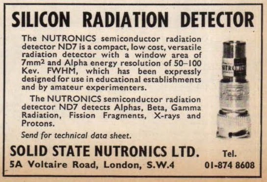
Here they are -
 |
| Please help beat cancer - DONATE click above |
Unrelated to this post, below the following novel advert, is an example of
eclectic science esoterica
The Ernest Glitch Chronicles.
A STEAMPUNK NOVEL, FULL OF
ANARCHIC EXPERIMENTAL SCIENCE
"Hodges emitted a scream the like of which
I hadn't heard since his scrotum was burned off
during my experiment with fluorine gas last year."
The Exotic Experimentation of Ernest Glitch,
Victorian Science with a Smile
Sample chapters here or buy the book now!
 |
Search for Ernest Glitch on your Kindle
or buy now -
UK (77 pence) here
USA (99 cents) here
|
photo Rob Lavinsky

Gem Quality Natural Aluminium Oxide Crystal
| Main Menu - click above |